


News Center
--
Because of the reform and the birth, because of the reform and prosperity, because of the reform and strong
Innovative Measures in the Xi’an–Chongqing High-Speed Railway Project: Dongfeng Rail Leads the Wave of Railway Innovation
Nov 06,2024
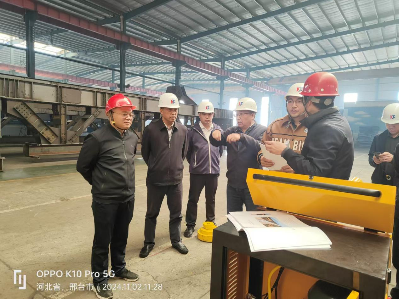
Technical representatives from China Railway Construction Fifth Survey and Design Institute visited Hebei Dongfeng Shijing Rail Transit Co., Ltd. to conduct a static load test on the Renhe Bridge on the Ankang–Chongqing section of the Xi’an–Chongqing High-Speed Railway, a railway project in which China Railway 12th Bureau Group Co., Ltd. is a participating contractor. The purpose of this visit is to ensure that this critical component of the railway project meets the anticipated safety and performance standards. As the first such test of its kind nationwide, the primary objective is to verify that this key section of the railway project complies with the required safety and performance criteria.
Project Overview:
The main girder of this project has a length of 641.6 m and is constructed as a prestressed concrete single-box, single-cell constant-depth box girder. The box cross-section is designed with a constant depth corresponding to the outer contour, with a girder height of 11 m, a box width of 13.9 m, a top width of 15.4 m, and a bottom width of 15.4 m.
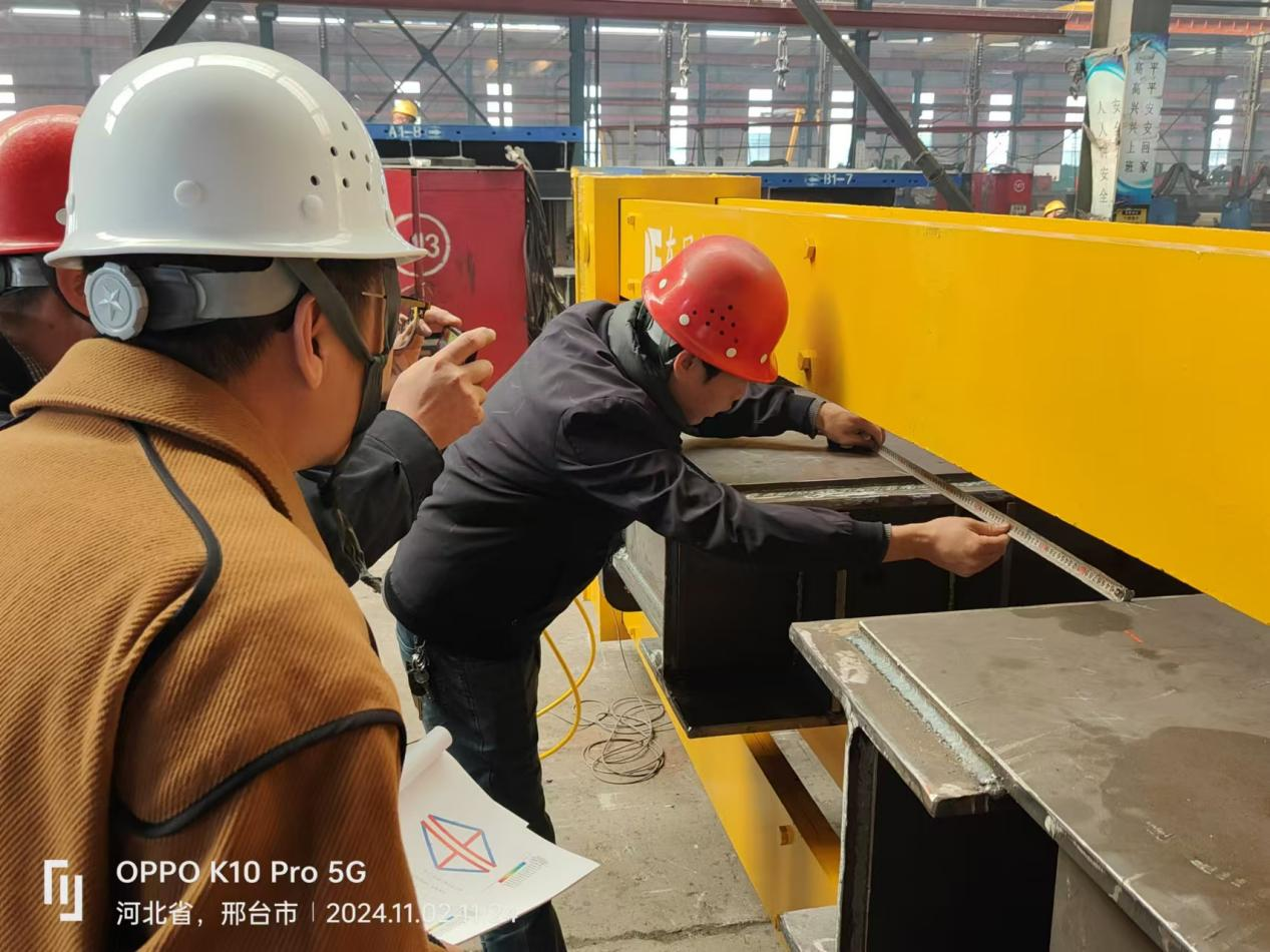
Prior to the construction of the cantilever segment, all cantilever members must undergo trial assembly and load testing; they may only be used once it has been confirmed that they meet the service requirements. During the load test of the main members, deflection and deformation under the corresponding loads shall be measured to determine the pattern of elastic deformation, thereby providing a reliable basis for the cantilever concrete placement construction of the box girder.
In view of the bridge pier’s great height and the constrained construction site, and in light of the design characteristics of the member-based structure—namely its simplicity and well-defined load distribution—the suspended formwork system is assembled on the ground after fabrication, and load tests are conducted on the main truss, upper and lower transverse girders, front and rear suspenders, and suspender connectors.
Test method:
Main truss preloading:
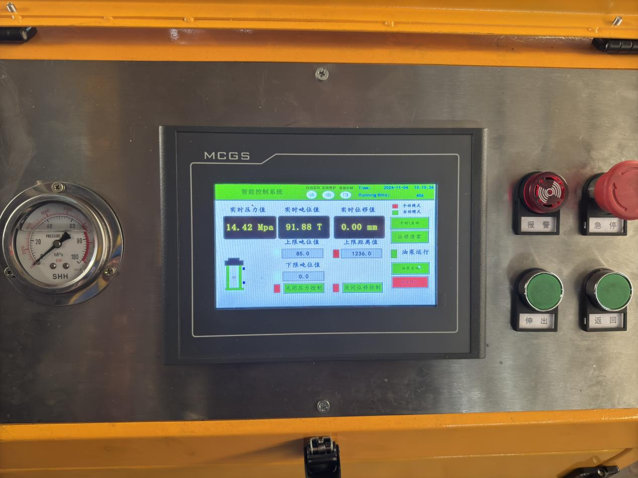
The main truss is laid horizontally on two H600 steel girders, with the front end secured using a beam-and-sling system and steel lifting slings. Loading is applied using a 400-ton jack, with the maximum load limited to 285 tons and staged in three increments: 60% (171 tons), 80% (228 tons), and 100% (285 tons).
Front lower crossmember test:
Place the front lower transverse beam horizontally on two W25b I-beams, and use 200-ton hydraulic jacks to apply loads to each tension connection node according to the design load, with loading staged in three increments: 60%, 80%, and 100%.
Rear lower crossmember test:
Place the rear lower transverse beam horizontally on top of two 25b I-beams, and use a 200-ton jack to apply loads to each tension connection node according to the design load, with loading staged in three increments: 60%, 80%, and 100%.
Front upper crossbeam test:
Place the front upper transverse beam horizontally on two 45b I-beams, and apply loads at each lifting point using 100-ton hydraulic jacks. The loading will be staged in three increments: 60%, 80%, and 100% of the design load.
Suspension rod and suspension rod adapter testing:
Insert the suspension rod and its adapter into a φ299×25 seamless steel pipe, then install washers and nuts. Apply loading at one end using a 400-ton jack, with loading staged in three levels: 60%, 80%, and 100%.
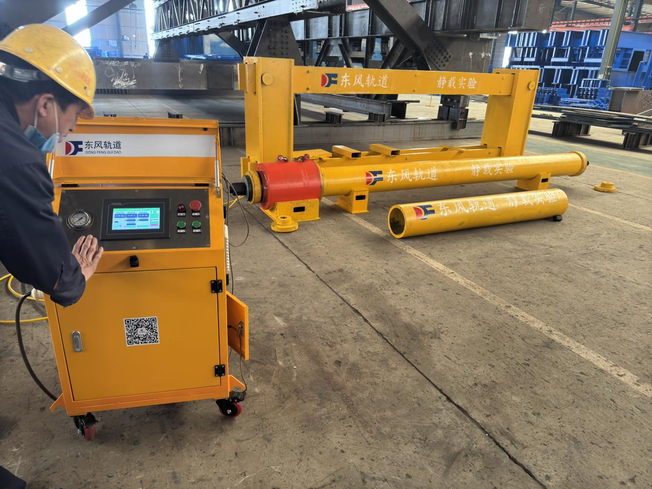
Through this static load test, we successfully ensured the structural strength and stability of the railway bridge’s main truss, thereby providing a solid foundation for the safe operation of the railway bridge.

Hotline:


Fax:

Email:
Hebei Dongfeng Shijing Railway Co., Ltd.
Company culture:What others cannot do, we can do; what others can do, we will do better.
Enterprise mechanism: quality training, selection and appointment, strict management, positive incentives.
Enterprise Management: Principles in major matters, understanding in small matters, cooperation in handling matters.
Message Board
We will contact you within one working day. Please check your email.