


News Center
--
Because of the reform and the birth, because of the reform and prosperity, because of the reform and strong
A Method for Fabricating a Bridge Static Load Testing Bench
Nov 03,2021
In bridge construction projects, a specified number of fabricated bridges must be selected for static load testing to ensure that their quality meets the relevant technical requirements. A static load testing rig is the equipment that provides the test load for such tests. Currently, most static load testing rigs in use are conventional steel-structure rigs designed based on the principle of internal-force self-balancing. Next, let us take a closer look at a type of bridge Static Load Test Bench Let’s talk about the method of making it!
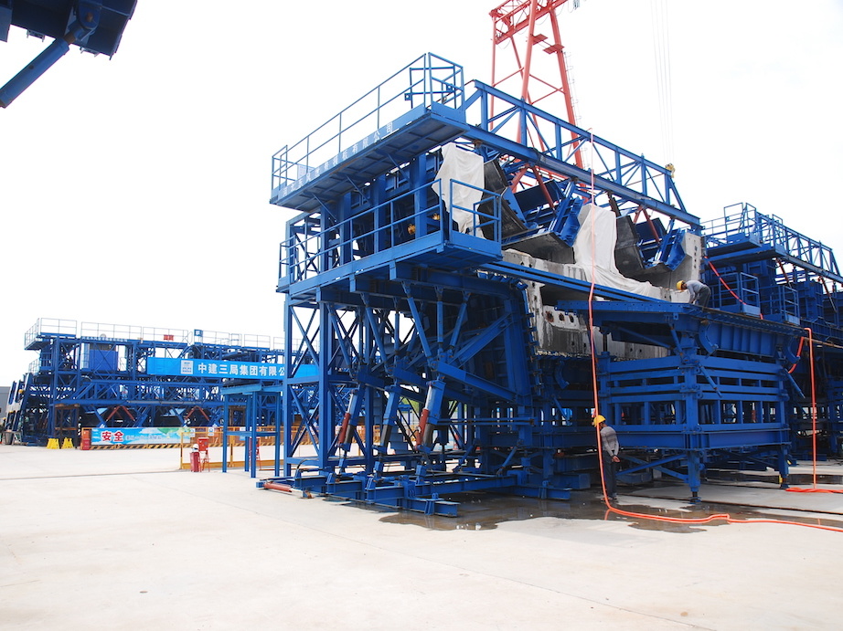
The main drawbacks of the static load testing rig are:
1) During the static load testing of the bridge, a hole must be drilled in the bridge’s flange to accommodate the longitudinal rod, thereby causing unnecessary damage to the bridge;
2) Some are designed based on the principles of leverage and self-balancing, and are pore-free. Static Load Test Bench This applies only to conventional static load tests, in which the test load is significantly lower than that used in fracture tests; moreover, high-load fracture tests lack a reusable static load testing rig.
3) Currently, conventional static load testing rigs for open-web steel structures are unable to effectively address the misalignment between the support centerline and the web centerline, thereby compromising the accuracy of the test results.
Technical implementation elements of the static load test bench:
Accordingly, the objective of the present invention is to enable the reaction-frame system to accommodate both conventional static-load tests and high-load failure tests by adjusting the number of stages in the reaction frame, thereby making it suitable for use as a static-load failure test rig for bridges subjected to high loads applied by multiple jacks. Furthermore, through rational structural design, the invention addresses the issue of misalignment between the centerline of the test rig’s support platform and the centerline of the bridge’s web.
The embodiments of the present invention provide the following bridge static load testing rig.
Reaction frame on the bridge
Two end beams fixed to one end of the aforementioned reaction frame;
At least four bridge support piers are provided, with one set of such piers arranged beneath each end of the bridge; the two sets of bridge support piers are equal in number and are symmetrically positioned on either side of the cross-sectional centerline of the bridge web.
A ground-mounted pole beam is provided; and the bridge is supported on the pole beam via a bridge support platform.
Multiple jacks are configured to apply loads to the test bridge; static load testing rig
A plurality of jack beams fixedly installed beneath the reaction frame, and a corresponding plurality of jack beams for each of the jacks, wherein the jack beams are configured to be in contact with the jacks; then
Multiple tie rods, by rigidly connecting the end girder and the rod girder, connect the bridge. Static Load Test Bench and form a closed-force system with the aforementioned bridge;
Here, one end of the aforementioned rod and beam is connected to the aforementioned steering tie rod, while the other end extends along the longitudinal axis of the bridge.
Prefer the aforementioned reaction frame,
A lower reaction frame, with both ends fixedly connected to the end beam; and
An upper reaction frame positioned directly above the lower reaction frame, and a detachable connection between the upper and lower reaction frames; the lower reaction frame comprises a third reaction beam and a fourth reaction beam.
The third reaction beam is positioned directly above the first reaction beam, and the fourth reaction beam is positioned directly above the second reaction beam; the aforementioned first and second reaction beams are symmetrically arranged on either side of the bridge web centerline, while the aforementioned third and fourth reaction beams are also symmetrically arranged on either side of the bridge web centerline; static load test stand
The end beams are respectively and perpendicularly fixed to one end of the first reaction beam and one end of the second reaction beam.
The aforementioned upper reaction frame is connected to the aforementioned lower reaction frame when the test conditions satisfy the first condition.
The foregoing description sets forth a method for constructing a static load testing rig for bridges; however, it is not intended to limit the scope of the present invention. To those skilled in the art, various modifications and variations may be made to the invention. Any modifications, equivalent substitutions, or improvements made within the spirit and principles of the present invention shall be deemed to fall within the scope of protection thereof.

Hotline:


Fax:

Email:
Hebei Dongfeng Shijing Railway Co., Ltd.
Company culture:What others cannot do, we can do; what others can do, we will do better.
Enterprise mechanism: quality training, selection and appointment, strict management, positive incentives.
Enterprise Management: Principles in major matters, understanding in small matters, cooperation in handling matters.
Message Board
We will contact you within one working day. Please check your email.