


News Center
--
Because of the reform and the birth, because of the reform and prosperity, because of the reform and strong
Construction Technology for Fixed Reaction Frame Static Load Testing Stand
Oct 29,2021
The static load testing rig is a non-destructive test used to evaluate the crack resistance, deflection, and stiffness of precast T-beams, while Static Load Test Bench It is once again an essential piece of infrastructure for static load testing. Currently, fixed reaction-frame static-load test bases offer advantages such as a short construction period, low cost, and ease of installation. In China, precast T-beam static-load test bases are broadly categorized into two types: fixed reaction-frame static-load test bases and large-scale monolithic static-load test bases; however, the associated construction techniques still require further in-depth research. Therefore, let us now explore the construction technology for fixed reaction-frame static-load test rigs!
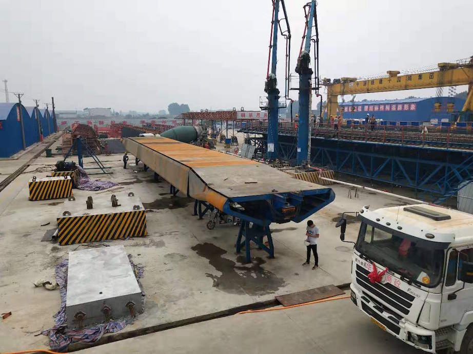
I. Principle of the Fixed Reaction Frame Test Bed
Fixed Reaction Frame Static Load Test Bench This structure provides the load and support required for the static load test on the beam. The test jack is installed between the top of the beam and the upper reaction frame, with the upper reaction frame serving as the reaction point for the jack. The upper structure and the lower foundation are connected via link rods and high-strength bolts, forming a relatively closed architectural test base system. The connecting rods, together with the lower foundation, collectively resist the uplift and tensile forces generated during the test; by means of the jack’s lifting action, the required load for the static load test is applied, thereby providing the reaction load necessary for the test.
II. Preliminary Preparations for the Fixed Reaction Frame
I) Location Selection
The placement of the reaction-force support structure’s static-load base should be given full consideration during the preliminary planning phase of the girder yard.
2.1.1 Gantry cranes and other lifting equipment are easy to operate flexibly, and the test girders are convenient for lifting and storage;
2.1.2 Select an area with minimal environmental interference and low susceptibility to external vibration. Static load test stand
2) Steel Component and Reinforcement Processing
2.2.1 Selection and Fabrication of Steel Components
1) A hollow-web truss is adopted. Its cross-section is fabricated by welding 40# channel sections made of Q345 steel with 20-mm-thick steel plates. Since all nodes in the hollow-web truss are rigid, the chord members will be subjected to bending and shear. The design should be coordinated with that of the rigid frame beams; the bracing members, acting as columns in the rigid frame, should be designed as rigid columns, with an H-shaped section being a suitable choice.
2) The bolt holes in the connecting rods shall be produced by mechanical punching, with hole diameter and positional accuracy within 2 mm, to ensure the stability of the overall steel structure during testing as well as the ease of disassembly and installation of the steel structural components.
2.2.2 Prior to rebar processing, straightening must be performed to remove surface rust, scale, oil stains, and other contaminants, with an allowable deviation of no more than 10 mm. Static load testing stand
3) Geological surveying and treatment of poor foundations;
After the site has been selected, geological exploration shall be conducted on the geology of the selected site. For example, the design load may be multiplied by a certain safety factor before being adopted. Appropriate foundation treatment methods shall be employed, such as the overburden method, preloading method, dynamic compaction and replacement method, vibroflotation method, soil–cement mixing method, and high-pressure jet grouting method, with the foundation bearing capacity and the maximum test load determined based on actual conditions. Static load testing rig
III. Foundation Construction for the Fixed Reaction Frame
(1) Digging a Hole
3.1.1 Prior to drilling, close attention should be paid to the weather forecast, and drilling operations should be scheduled during periods with minimal rainfall whenever possible, concentrating resources to complete the drilling in a single phase. Based on the soil conditions at the site and the length and width of the excavation, the slope protection coefficient shall be determined, and appropriate slope protection measures shall be implemented to ensure the stability of the excavation and facilitate subsequent construction; mechanical excavation shall be the primary method, and when the excavation reaches 20–30 cm below the design elevation, manual leveling and compaction of the foundation shall be carried out. 3.1.2 During excavation: static load test stand
3.1.3 When construction is carried out under harsh schedule conditions and during the rainy season, a circular drainage trench shall be excavated around the bottom of the shaft immediately after excavation of the foundation pit is completed. Sump wells shall be provided at the four corners to promptly drain accumulated water within the tunnel, and a 30-cm-high embankment shall be constructed at the tunnel entrance to prevent surface runoff from entering the tunnel.
(II) Excavation Pit Treatment
3.2.1 During excavation, the excavation elevation and dimensions of the foundation pit shall be reviewed repeatedly to prevent over-excavation or under-excavation. Upon completion of excavation, a bearing capacity test shall be conducted on the foundation; only after passing the test shall the foundation be compacted and leveled, followed promptly by placement of the leveling layer. The cushion layer shall be C20 concrete with a thickness of 10–15 cm.
(3) Installation Position of the Piston Rod and Reinforcement Tying
3.3.1 After the completion of grouting for the buffer layer, proceed with the positioning of the lower support rods. The accuracy of this positioning directly affects the stability of the superstructure and the success of the static load test, and therefore requires particular attention. Static load test stand
1) During the initial layout, to facilitate the lifting and installation of the girder, it is necessary to ensure the straightness of the entire test stand and the verticality of all gantry crane travel tracks.
2) Ensure that the horizontal and vertical deviations of the lower struts are both within 2 mm per meter. After connecting the lower struts to the lower beams, stability during concrete placement and subsequent construction cannot be guaranteed; therefore, ribs shall be provided on both sides of each lower connection strut for reinforcement, to prevent deformation and misalignment of the lower struts.
3) Reinforcement shall be tied using integral reinforcement mesh panels. When the position of the mesh panel conflicts with that of the underlying component, the position of the underlying component shall take precedence, and the reinforcement mesh panel shall be appropriately offset.
The foregoing describes the construction technology for fixed reaction-frame static-load test rigs, which has effectively addressed a series of longstanding challenges associated with conventional statically determinate T-beam load-testing platforms, including lengthy construction schedules, high costs, difficult site conditions, and extended pre-test preparation periods. As a result, this construction technique has gradually become the dominant approach for T-beam static-load testing. While the construction technology for the foundations of fixed reaction-frame static-load test rigs has grown increasingly mature in China, further in-depth research is still needed in the fabrication and installation of integral steel components. Enhancing the overall assembly and securing of these steel components will facilitate more efficient, scientifically sound, and economically viable construction practices that better meet contemporary demands.

Hotline:


Fax:

Email:
Hebei Dongfeng Shijing Railway Co., Ltd.
Company culture:What others cannot do, we can do; what others can do, we will do better.
Enterprise mechanism: quality training, selection and appointment, strict management, positive incentives.
Enterprise Management: Principles in major matters, understanding in small matters, cooperation in handling matters.
Message Board
We will contact you within one working day. Please check your email.